Fluid System & Check Valve Prototypes
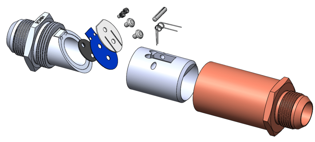
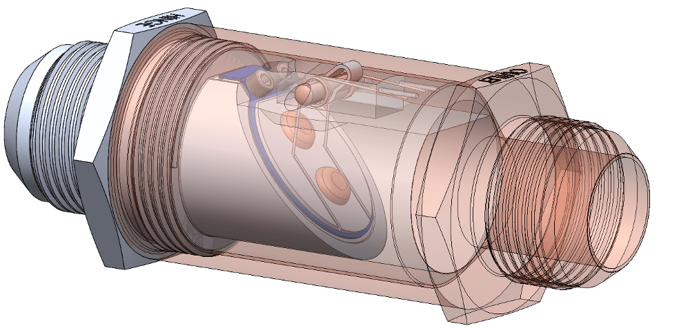
A fluid system to test a variety of check valve prototypes. Shown below is an exploded assembly of the final check valve prototype.
Check out more details about this project below.
Created SolidWorks CAD models of each component.
In the picture the following components were modeled:
- Inlet Housing (Gray)
- Shell (Translucent, White in the image above.)
- Outlet Housing (Orange)
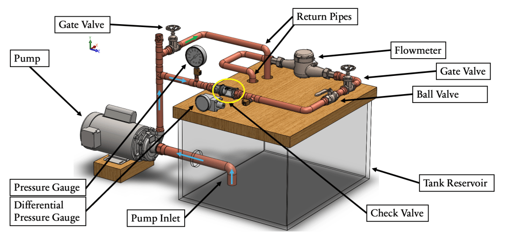
Created a SolidWorks CAD model of the test stand.
Did so using CAD models provided on McMaster-Carr and SolidWorks’ weldments feature.
Performed basic fluid mechanics calculations to find major and minor head losses caused by friction and fittings, as well as head gain produced by pump. This system is meant to have water running through it.
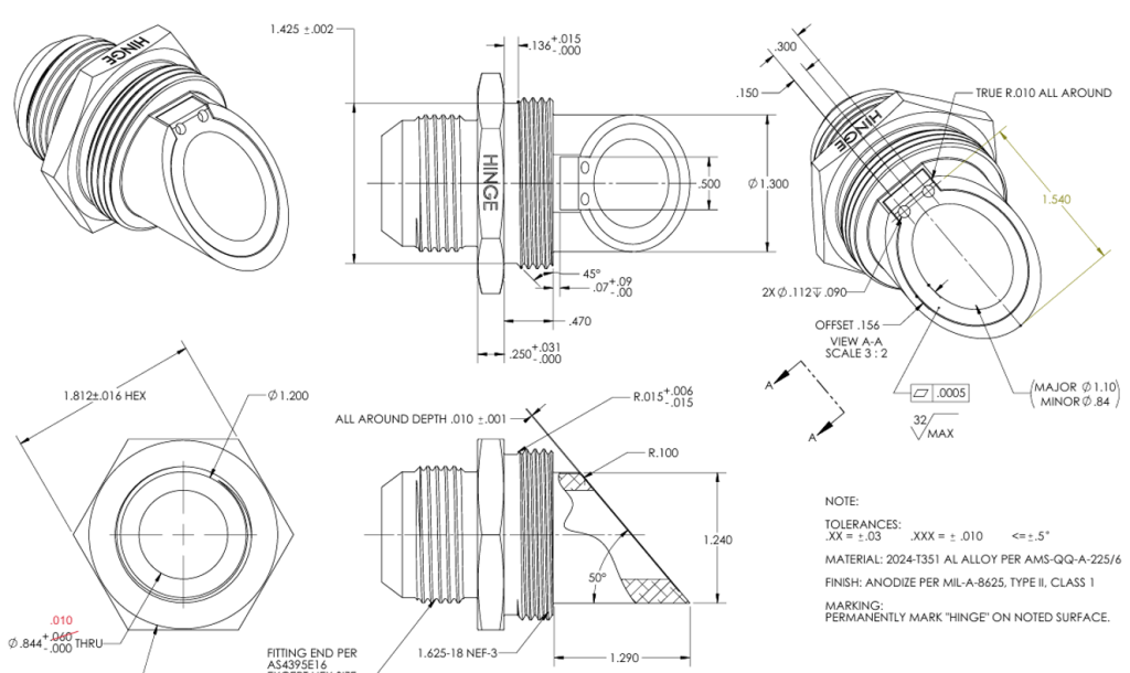
Inlet Housing Drawing
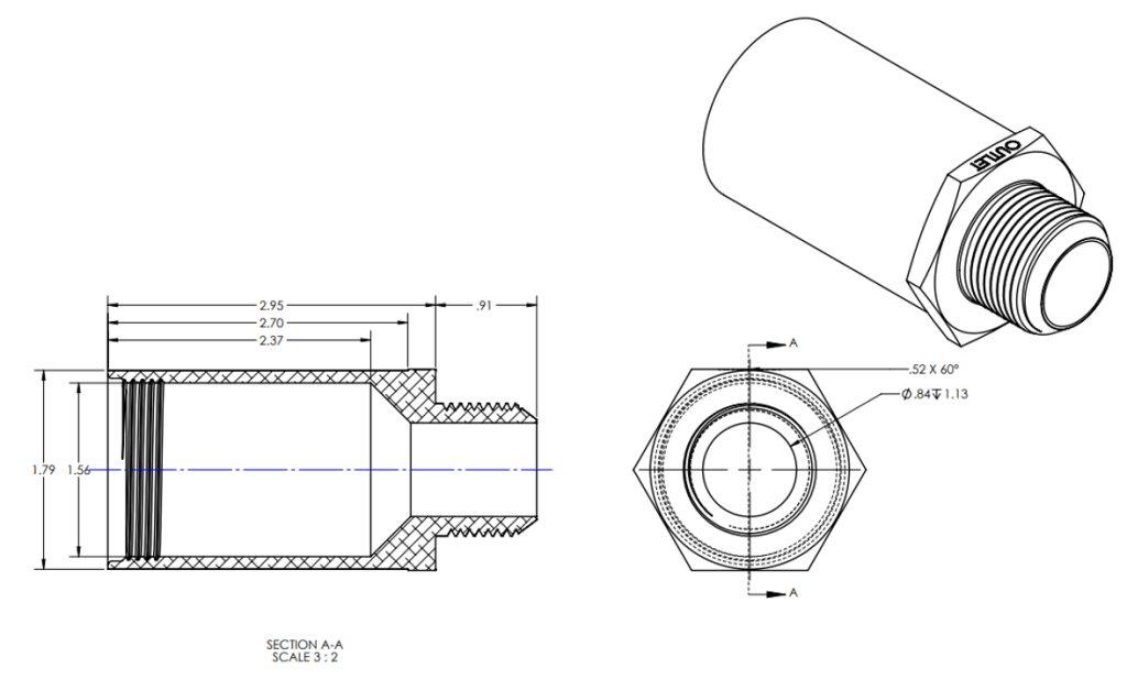
Outlet Housing Drawing
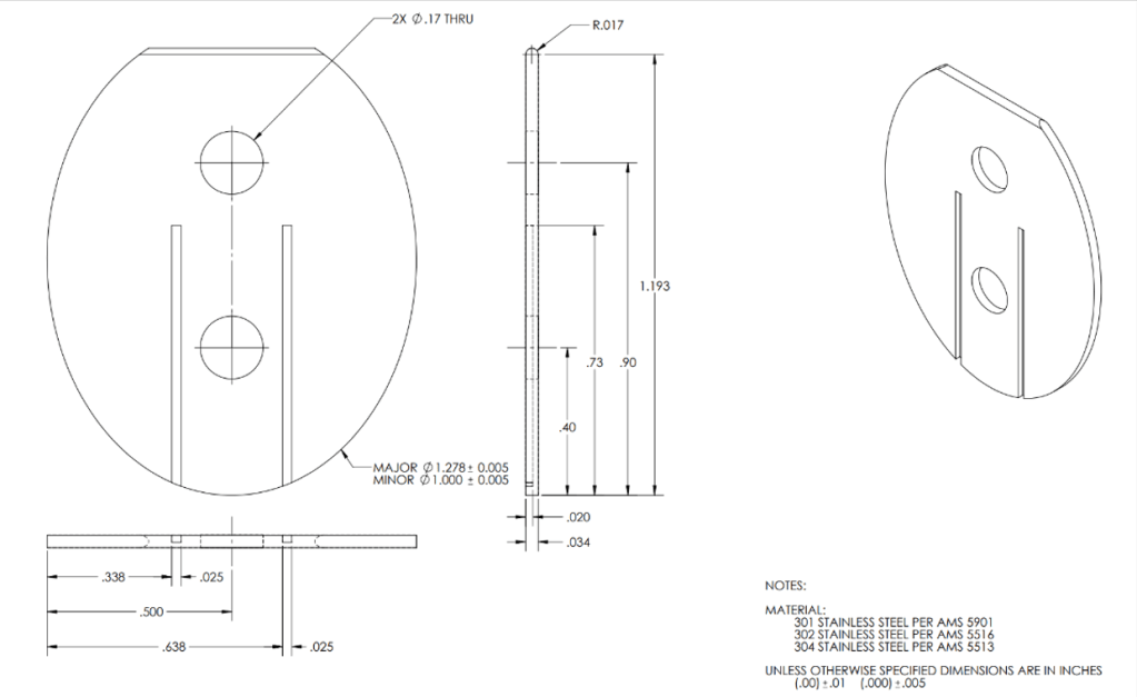
Seal Retainer Drawings
These are the parts that had to be manufactured. All other parts came ready to go.
Selected appropriate fluid system components on McMaster-Carr.
The pump seen on the right was deemed suitable as per the manufacturer pump curve diagram. Max pressure produced by this pump wasn’t expected to surpass 90 psi.
Some other components were also chosen:
- Pressure gauge (NPT connection) to measure operating pressure.
- Differential pressure gauge (NPT connection) to measure pressure drop.
- Flowmeter to measure operating mass flowrate.
- Gate valves to adjust the mass flowrate.

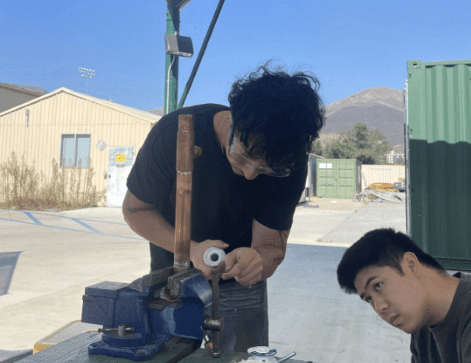
All teammates assisted in soldering the fluid system together.
Did so using solder wire, flux, a propane torch, and some effort.
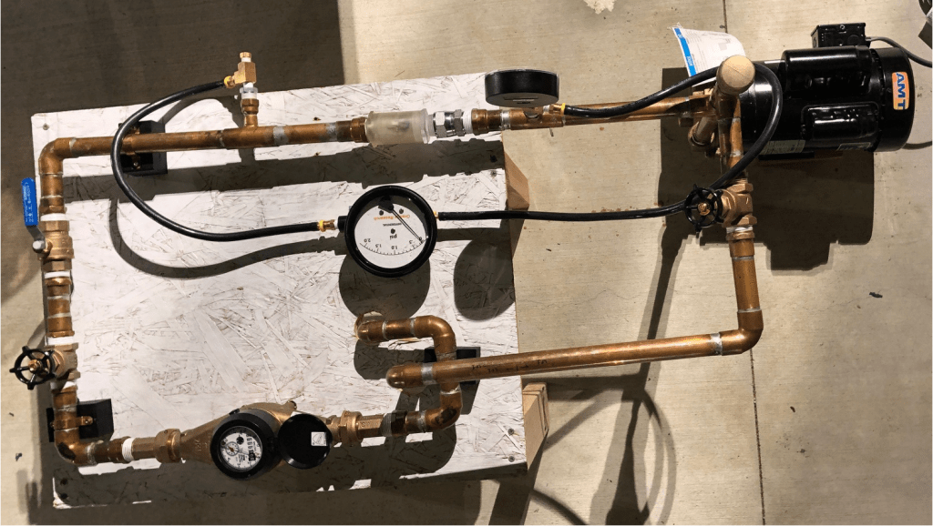
Testing
Seen in the picture is the fluid system fully build, ready for testing.
As a team, we were able to produce a swing check valve that had a pressure drop of 1.19 psi @ 30 GPM. This met our max pressure drop requirement of 1.5 psi.
There were most definitely some improvements we could have made, such as selection of fittings that sealed better.
A video of an early test run could be opened with the button below.