Knee Scooter
This course project began with the ideation phase, during which our team sketched several geometries that appeared to have the potential to be structurally sound. We eventually identified one that was and created a model of it on SolidWorks using the “Weldments” feature. We selected the appropriate material and created a finite element analysis (FEA) study, where we applied boundary conditions and the two extreme static load cases. One of which was on the handlebars and the other on the seat. The probe tool then allowed us to analyze the point of maximum stress and displacement.
We can’t assume the stress and displacement values given to us by the FEA software to be correct. Therefore, we picked to analyze the max displacement handlebar load case on paper, by hand. This verified that the values given by SolidWorks FEA were correct. We then built the scooter and tested the displacement values using a displacement gauge to find how accurate our analysis was.
Check out the results of this project below.
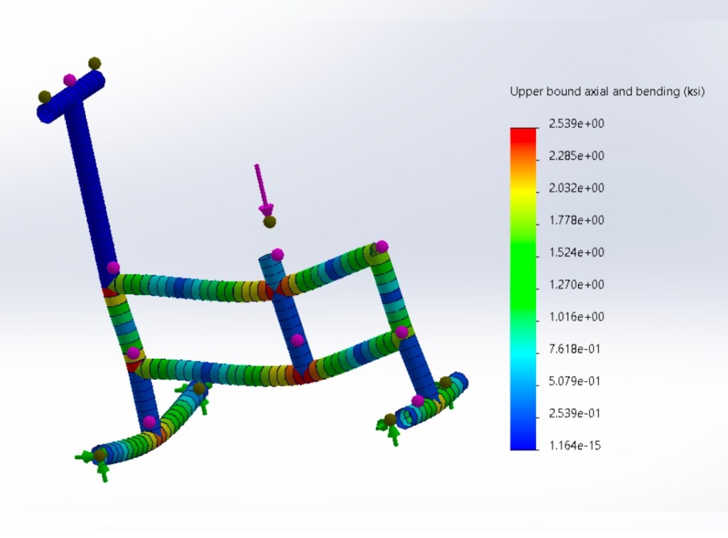
Load Case One
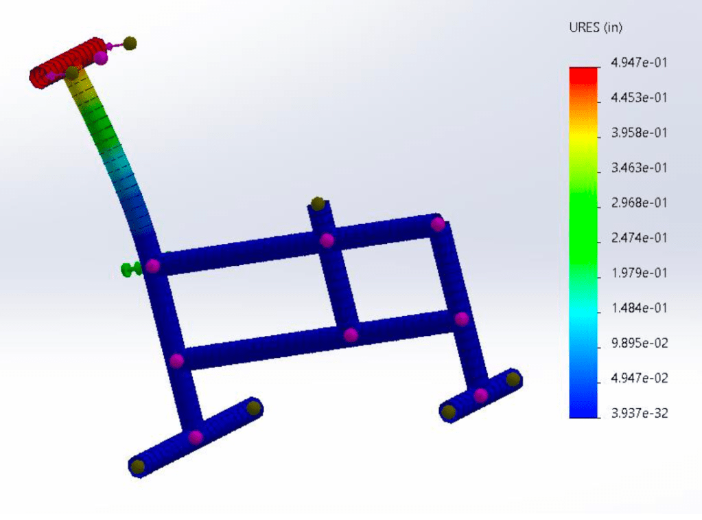
Analyzed the handle bar load case using the stress and displacement FEA plots. The stress FEA plot could be found through “Report PDF” and labeled as “Figure 5”.
Load Case Two
Analyzed the seat load case using the stress and displacement FEA plots. The displacement FEA plot could be found through “Report PDF” and labeled as “Figure 6”.
Testing
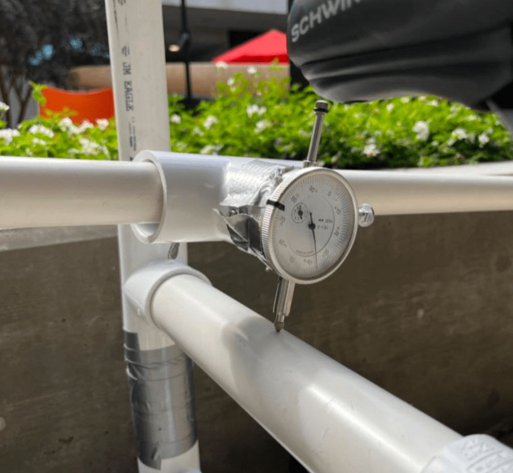
Tested using a displacement gauge, which allowed us to deduce a percent error of 12.4% between FEA and real life.
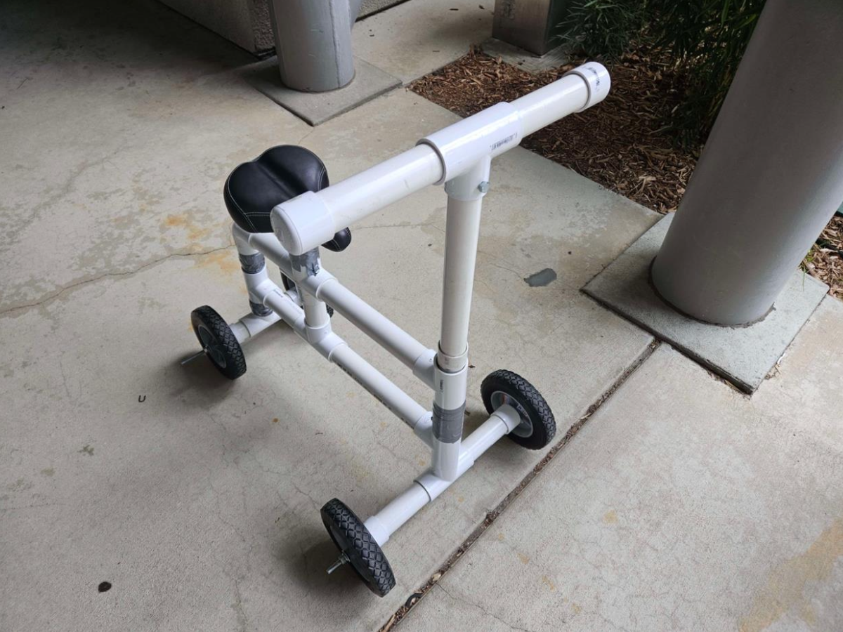
Final Product
A useable knee scooter accompanied with a final report that describes the design, manufacturing, assembly, and testing procedures. The report also provides justifications for the design choices and the application of material strength and stiffness theory.
Teammates are listed in the report.