Workbench
This project started with the ideation phase, where I sketched various geometries for the different parts of the workbench. Once the design was finalized, I created a CAD model in SolidWorks, which enabled me to produce detailed technical drawings that include dimensions and GD&T where needed. These drawings provide all the necessary information for anyone to replicate the workbench. I then constructed it using plywood, 2x4s, 2x6s, and 2x1s, utilizing a variety of power tools.
Check out the results of my work below.
Subassembly Drawings
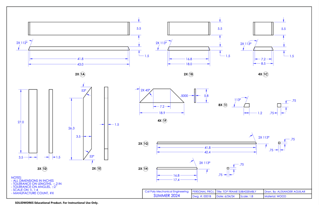
The subassembly drawing for the top frame. Subassembly drawings are denoted with a B that follows the part #.
Part Drawings
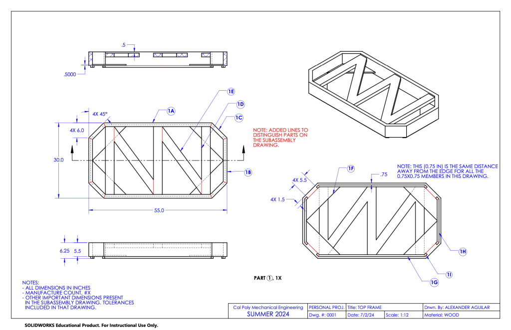
The part drawing for the top frame. Part drawings are denoted with only #’s.
Assembly Drawing
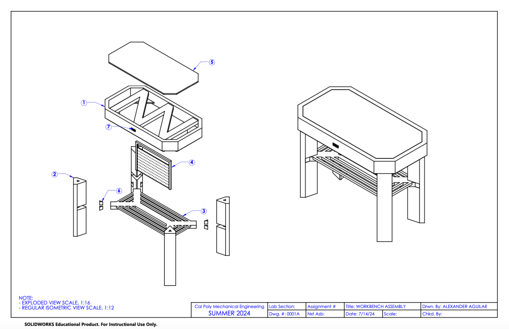
The complete assembly drawing. It shows 7 total parts that also have both subassembly and part drawings. Click on “Drawings PDF” to see the rest of them.
